


Product Overview
The ZH Chemical Self-Priming Pump-also known as the ZH Stainless Steel Corrosion-Resistant Chemical Self-Priming Pump or Self-Priming Chemical Centrifugal Pump-is a single-stage, single-suction, self-priming chemical centrifugal pump.
It offers high efficiency, reliable performance, low energy consumption, and low operating noise. The pump is suitable for conveying corrosive media with temperatures ranging from 0°C to 220°C and containing solid particles smaller than 3 mm.
For media containing particles or fibers larger than 3 mm, the ZW Non-Clogging Self-Priming Sewage Pump is recommended.
Model Designation
Example: ZH50-32-160A
|
Z |
Self-priming pump designation |
|
H |
Chemical centrifugal pump designation |
|
50 |
Pump suction inlet diameter, in mm |
|
32 |
Pump discharge outlet diameter, in mm |
|
160 |
Nominal impeller diameter, in mm |
|
A |
Impeller diameter trim designation, indicated by A, B, or C |
Product Features
1. High-Performance Self-Priming: "Prime Once, Self-Prime Throughout Service Life"
The pump features an axial liquid-return casing design. The casing consists of a suction chamber, liquid storage chamber, volute chamber, liquid-return passage, and gas-liquid separation chamber.
After the initial priming, no foot valve is required in the piping system. The pump can therefore achieve self-priming operation with simplified installation and convenient operation, significantly reducing the complexity of the piping system.
2. Efficient Gas-Liquid Separation and Short Self-Priming Time
After the pump starts normally, the impeller draws both the liquid contained in the suction chamber and the air in the suction line into the pump.
The liquid and air are mixed inside the impeller and form a gas-liquid mixture under centrifugal force. The mixture then enters the gas-liquid separation chamber through the diffuser pipe.
As the flow velocity suddenly decreases, the lighter gas is separated and discharged, while the deaerated liquid returns to the liquid storage chamber and re-enters the circulation process.
This process is repeated continuously. The air in the suction line is gradually removed until the suction line is completely evacuated and the self-priming process is completed.
3. Heavy-Duty High-Rigidity Shaft for Stable and Reliable Operation
The pump is equipped with an enlarged, high-rigidity pump shaft and three imported bearings, providing excellent rigidity and operational stability.
The pump runs smoothly and quietly, supporting long-term, continuous, and stable operation.
4. Combined External/Internal Mechanical Seal for Extended Service Life
The pump uses a combined external/internal mechanical seal design. Different sealing configurations, including double-ended mechanical seals, can be provided according to customer requirements.
A water-cooling system is also available to effectively reduce the temperature of the sealing faces and significantly extend mechanical seal service life.
5. Multiple Material Options for Broad Corrosion Resistance
Materials for wetted components can be selected according to the properties of the pumped medium. Available materials include:
- Cast iron
- Cast steel
- 1Cr18Ni9Ti
- 1Cr18Ni12Mo2Ti
- 316 stainless steel
- 316L stainless steel
For special operating conditions, the pump can also be manufactured using austenitic stainless steel, duplex stainless steel, Hastelloy, high-nickel alloys, and other customized materials.
This enables the pump to handle a wide range of corrosive media.
6. Suitable for Media Containing Solids
The pump can convey media containing solid particles smaller than 3 mm, with a solids concentration of up to 30%.
It is also suitable for media with viscosities of up to 100 cP, meeting the requirements of most slurry-handling applications in the chemical industry.
7. Direct-Coupled Synchronous Drive and Compact Design
The motor and pump shaft are connected either directly or through an extended coupling for synchronous transmission.
This design provides:
- Compact construction
- Reduced floor-space requirements
- Convenient installation and maintenance
Motors with IP54/IP55 protection and Class F insulation are suitable for outdoor installation, eliminating the need for a dedicated pump room.
Applications
The ZH Chemical Self-Priming Pump is widely used for conveying corrosive media with temperatures ranging from 0°C to 220°C and containing solid particles smaller than 3 mm.
It can handle clean water and seawater, as well as acidic or alkaline chemical liquids and general semi-pasty slurries.
Typical applications include:
- Chemical, acid-making, and alkali-making industries: Conveying acid, alkali, and salt solutions of various concentrations, as well as organic solvents
- Petrochemical industry: Conveying corrosive materials in petroleum refining and chemical processing plants
- Environmental protection and water treatment: Municipal environmental protection, industrial wastewater treatment, acid and alkaline wastewater neutralization, acid dosing processes, pond and river aquaculture, and municipal sewage discharge
- Electroplating and electrolysis: Conveying plating solutions, electrolytes, and pickling solutions
- Pharmaceutical and pesticide industries: Conveying pharmaceutical intermediates, pesticide concentrates, and various corrosive reaction media
- Textile dyeing and brewing: Conveying dyeing wastewater and corrosive dye solutions
- Power industry: Conveying equipment cooling water and desulfurization-system media
- Paper industry: Conveying pulp bleaching solutions and various corrosive chemicals
- Food industry: Conveying corrosive cleaning solutions and process media used in food processing
- Construction and firefighting: Booster water supply for building fire protection systems and temporary emergency drainage
- Agriculture and landscaping: When equipped with a rotary-arm sprinkler, the pump can spray water into the air and disperse it into fine droplets. It is suitable for farms, nurseries, orchards, and tea plantations
- Filter press systems: The pump can be configured as a non-clogging self-priming sewage pump for use with various types of filter presses
Technical Specifications
1. Design Standards
The product is designed and manufactured in accordance with applicable domestic industry standards. The wetted components and installation dimensions can be customized according to customer requirements.
2. Operating Principle
The ZH Self-Priming Pump adopts an external-mixing self-priming structure with axial liquid return.
The pump casing consists of a suction chamber, liquid storage chamber, volute chamber, liquid-return passage, and gas-liquid separation chamber.
After the pump starts, the impeller draws both the liquid stored in the suction chamber and the air in the suction line into the pump. The liquid and air are mixed inside the impeller and, under the action of centrifugal force, flow toward the outer edge of the volute while carrying the air along with them.
A white foam band and a high-speed rotating liquid ring are formed around the outer edge of the impeller. The gas-liquid mixture then enters the gas-liquid separation chamber through the diffuser pipe.
As the flow velocity suddenly decreases, the lighter gas separates from the mixture and is discharged through the pump outlet. The deaerated liquid returns to the liquid storage chamber and re-enters the impeller through the liquid-return passage, where it mixes again with newly entrained air from the suction line.
This process continues repeatedly. The amount of air in the suction line gradually decreases until the air is completely evacuated and the self-priming process is completed. The pump then enters normal operating mode.
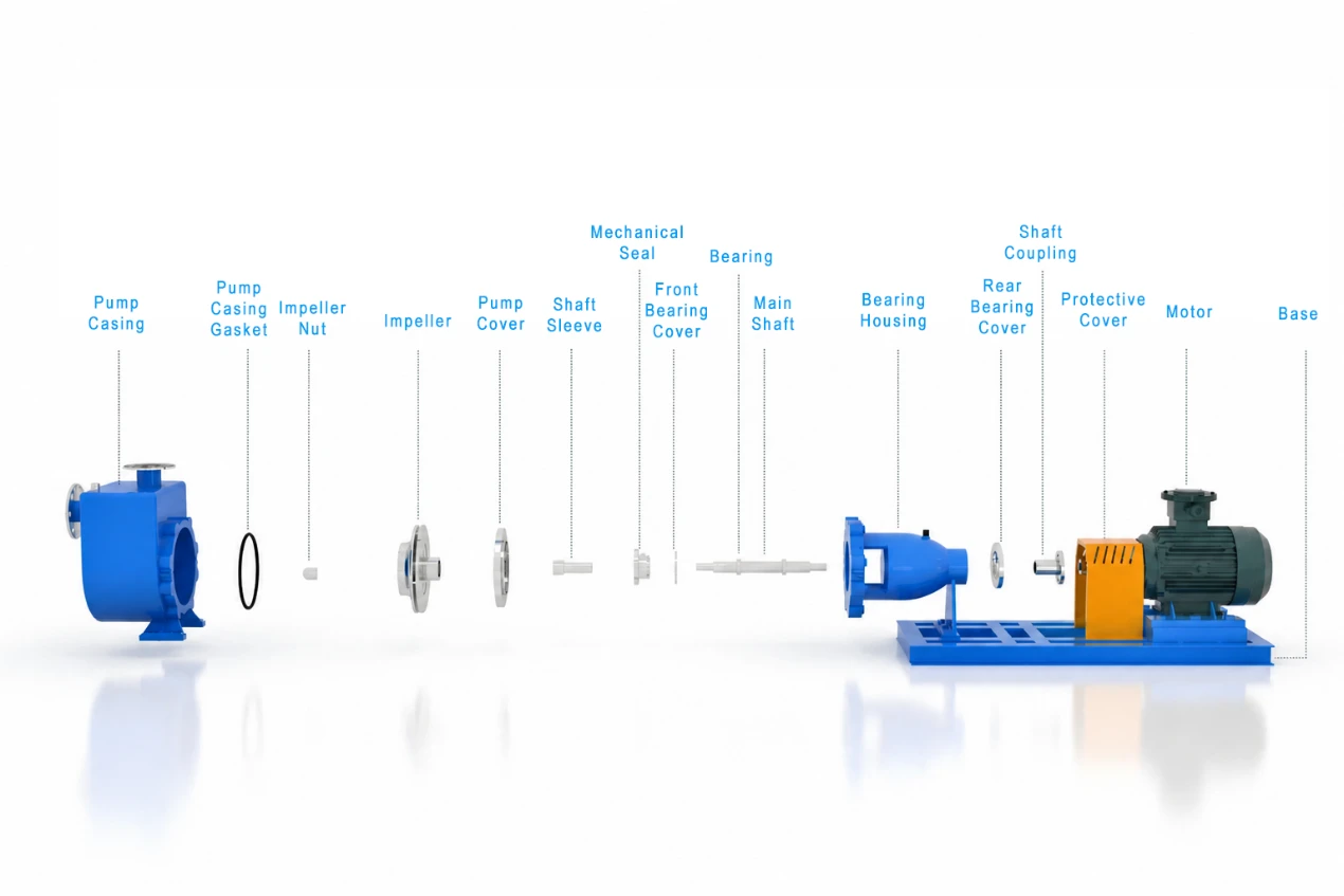
3. Main Components
The pump mainly consists of the following components:
- Pump casing
- Impeller
- Pump cover
- Pump shaft
- Bearing bracket
- Mechanical seal
- Shaft sleeve
An inlet check valve is installed on the pump casing to prevent liquid backflow when the pump is shut down.
4. Shaft Sealing System
The pump uses a combined external/internal mechanical seal. Users can select either a single mechanical seal or a double mechanical seal according to their operating requirements.
Flushing and cooling water at a specified pressure can be introduced into the seal chamber to lubricate and cool the seal faces.
5. Direction of Rotation
When viewed from the suction end of the pump, the impeller rotates counterclockwise.
6. Material Selection for Wetted Components
The materials for wetted components can be selected according to the characteristics of the pumped medium and the operating conditions.
|
Material |
Typical Application |
|
HT200 cast iron |
Neutral media and general clean water |
|
Cast steel |
General industrial media |
|
1Cr18Ni9Ti / 321 stainless steel |
General corrosive media |
|
1Cr18Ni12Mo2Ti / 316Ti stainless steel |
Conditions involving chloride ions and pitting corrosion |
|
304/304L stainless steel |
Moderately corrosive operating conditions |
|
316/316L stainless steel |
Highly corrosive media |
|
Duplex stainless steel |
Severe corrosion and abrasive conditions |
|
Hastelloy |
Extremely corrosive conditions, including strong acids and alkalis |
The material selection should be confirmed based on the actual chemical composition, temperature, concentration, solids content, and corrosiveness of the pumped medium.
7. Operating Conditions
The standard operating range is as follows:
|
Parameter |
Specification |
|
Flow rate, Q |
1.6–550 m³/h, covering the complete range of standard and trimmed-impeller models |
|
Head, H |
5–125 m; varies according to pump model |
|
Speed, n |
1,450 / 2,900 rpm; direct motor drive or variable-frequency speed control |
|
Suction lift / self-priming height |
5–6.5 m under clean-water conditions |
|
Medium temperature |
0–220°C; maximum allowable temperature varies according to material selection |
|
Solids concentration |
≤30%, up to 35% under suitable conditions; particle size below 3 mm |
|
Medium viscosity |
≤100 cP |
|
Port diameter range |
25–300 mm for suction and discharge ports |
|
Motor power |
0.55–132 kW, calculated according to the density and viscosity of the pumped medium |
Actual operating performance should be determined based on the selected pump model and the specific properties of the pumped medium.
8. Installation Guidelines
a. Piping Support
The suction and discharge piping must be provided with independent supports. The pump must not be used to support the piping system.
b. Foundation and Alignment
Before installation, use a spirit level to align and level the pump unit. Grout the foundation and anchor-bolt holes with concrete.
c. Coupling Alignment
The coupling alignment requirements are as follows:
The difference in the outer circumference measured at the top, bottom, left, and right must not exceed 0.1 mm.
The end-face clearance variation during one complete rotation must not exceed 0.3 mm.
d. Piping Diameter
The suction piping should have the same nominal diameter as the pump suction inlet.
The discharge piping diameter must not be smaller than the pump discharge outlet diameter.
e. Initial Filling
After installation, fill the pump completely with liquid through the filling port on the top of the pump before starting it.
5. Start-Up and Operating Precautions
The following requirements should be observed during start-up and operation:
a. Initial Priming
Before the first start-up, fill the pump casing completely with liquid. No further filling is required for subsequent start-ups under normal operating conditions.
b. Cooling Water and Manual Inspection
Turn on the cooling water. Rotate the coupling by hand to confirm that there is no rubbing, obstruction, or abnormal resistance.
c. Start-Up Procedure
Start the motor while loosening the filling-port cap slightly to facilitate air venting.
Open the discharge valve slightly. After the pump begins discharging liquid, gradually adjust the valve and tighten the filling-port cap.
Under normal conditions, the time from start-up to liquid discharge is approximately 2–10 minutes.
d. Temperature Monitoring
Regularly check the temperature rise of the bearings and motor.
The bearing temperature rise must not exceed 75°C.
e. Abnormal Noise or Operating Conditions
The pump should operate without abnormal noise.
Stop the pump immediately and inspect it if any unusual noise, vibration, leakage, or other abnormal condition occurs.
Structural Drawings
Performance Data Tables
|
Model |
Speed: n = 2,900 rpm |
Speed: n = 1,450 rpm |
||||
|
Flow Rate (m³/h) |
Head |
Motor Power (kW) |
Flow Rate (m³/h) |
Head (m) |
Motor Power (kW) |
|
|
ZH25-25-125 |
3.2 |
20 |
1.1 |
1.6 |
5 |
0.55 |
|
ZH25-25-160 |
3.2 |
32 |
2.2 |
1.6 |
8 |
0.55 |
|
ZH25-25-200 |
3.2 |
50 |
5.5 |
1.6 |
12.5 |
0.75 |
|
ZH25-25-250 |
3.2 |
80 |
7.5 |
1.6 |
20 |
1.5 |
|
ZH40-32-125 |
6.3 |
20 |
1.5 |
3.2 |
5 |
0.55 |
|
ZH40-32-160 |
6.3 |
32 |
3 |
3.2 |
8 |
0.55 |
|
ZH40-32-200 |
6.3 |
50 |
5.5 |
3.2 |
12.5 |
1.1 |
|
ZH40-32-250 |
6.3 |
80 |
11 |
3.2 |
20 |
2.2 |
|
ZH50-32-125 |
12.5 |
20 |
3 |
6.3 |
5 |
0.55 |
|
ZH50-32-160 |
12.5 |
32 |
4 |
6.3 |
8 |
0.55 |
|
ZH50-32-200 |
12.5 |
50 |
7.5 |
6.3 |
12.5 |
1.1 |
|
ZH50-32-250 |
12.5 |
80 |
15 |
6.3 |
20 |
2.2 |
|
ZH65-50-125 |
25 |
20 |
4 |
12.5 |
5 |
0.55 |
|
ZH65-50-160 |
25 |
32 |
7.5 |
12.5 |
8 |
1.5 |
|
ZH65-40-200 |
25 |
50 |
11 |
12.5 |
12.5 |
2.2 |
|
ZH65-40-250 |
25 |
80 |
22 |
12.5 |
20 |
3 |
|
ZH65-40-315 |
25 |
125 |
37 |
12.5 |
32 |
5.5 |
|
ZH80-65-125 |
50 |
20 |
7.5 |
25 |
5 |
0.75 |
|
ZH80-50-160 |
50 |
32 |
11 |
25 |
8 |
1.5 |
|
ZH80-50-200 |
50 |
50 |
18.5 |
25 |
12.5 |
2.2 |
|
ZH80-50-250 |
50 |
80 |
37 |
25 |
20 |
4 |
|
ZH80-50-315 |
50 |
125 |
75 |
25 |
32 |
7.5 |
|
ZH100-80-125 |
100 |
20 |
15 |
50 |
5 |
1.5 |
|
ZH100-80-160 |
100 |
32 |
22 |
50 |
8 |
2.2 |
|
ZH100-65-200 |
100 |
50 |
37 |
50 |
12.5 |
4 |
|
ZH100-65-250 |
100 |
80 |
55 |
50 |
20 |
5.5 |
|
ZH100-65-315 |
100 |
125 |
75 |
50 |
32 |
11 |
|
ZH125-100-200 |
200 |
50 |
55 |
100 |
12.5 |
7.5 |
|
ZH125-100-250 |
200 |
80 |
75 |
100 |
20 |
11 |
|
ZH125-100-315 |
200 |
125 |
110 |
100 |
32 |
15 |
|
ZH125-100-400 |
- |
- |
- |
100 |
50 |
30 |
|
ZH150-125-250 |
- |
- |
- |
200 |
20 |
18.5 |
|
ZH150-125-315 |
- |
- |
- |
200 |
32 |
30 |
|
ZH150-125-400 |
- |
- |
- |
200 |
50 |
45 |
|
ZH200-150-250 |
- |
- |
- |
400 |
20 |
37 |
|
ZH200-150-315 |
- |
- |
- |
400 |
32 |
55 |
|
ZH200-150-400 |
- |
- |
- |
400 |
50 |
75 |
If you cannot find the required specifications or model in our product range, please contact us at any time. Our technical specialists will provide prompt model selection assistance and a customized technical solution.
Hot Tags: zh self-priming pump, China zh self-priming pump manufacturers, factory


